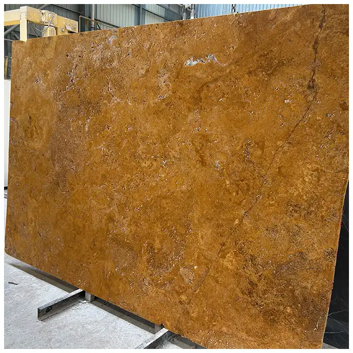
Quartzite Translucency Mapping before Backlighting and Cutting
The slab looks silver-grey under the warehouse roof. Then a narrow inspection light moves behind one pale band, and the band turns almost amber at its edge. A dark mineral bridge stays black. Beside it, quartz crystals hold the light for a moment before releasing it into the room. The response is not even, and that is what makes it worth studying.
I begin quartzite translucency mapping by refusing one simple question: “Is this slab translucent?” A slab is not a light switch. It contains zones with different mineral composition, thickness, fissures, repairs, and back conditions. Some areas transmit light. Others absorb or scatter it. The map records those differences before the strongest part of the slab is cut away.
The direct answer is to test the whole face with a repeatable light source, mark the response by slab coordinates, and overlay the proposed panels. Only then should the lighting designer fix the cavity, LED arrangement, diffuser, access, and controls.
Why Quartzite Translucency Mapping Must Cover the Whole Face
Translucency means light passes through a material but is scattered so objects behind it are not seen clearly. The optical distinction is outlined in transparency and translucency. In natural quartzite, the response depends on mineral composition, crystal size, thickness, microstructure, fissures, resin, reinforcement, and the wavelength and intensity of the light.
Quartz-rich areas may carry light
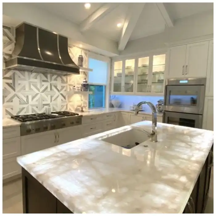
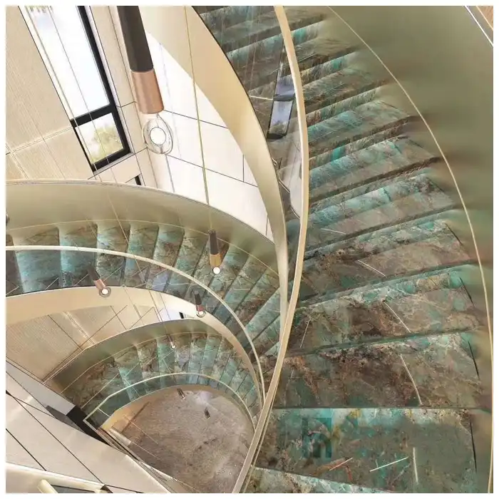
Clean pale quartz zones can allow light to enter and scatter through the stone. Their edges may glow more strongly than their center because thickness or mineral density changes. A crystalline pocket can look milky under front light and become warm, almost honeyed, under transmitted light.
The first pass of quartzite translucency mapping should mark broad zones rather than pretend to measure laboratory transmission. I use clear categories such as strong, moderate, low, and opaque under the recorded test condition. That language is honest enough for layout decisions and precise enough to identify where a larger mock-up is required.
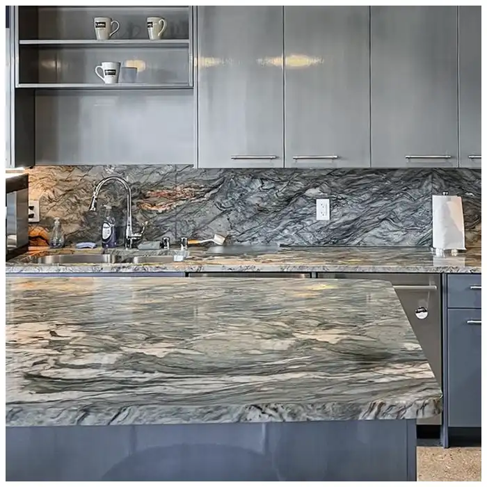
A Cristallo Blue quartzite face may contain pale translucent structures beside blue-grey and darker mineral passages. Backlighting can reveal that internal depth. It can also expose every interruption, including a repair line that looked quiet under normal room light.
Dark minerals create natural silhouettes
Mica-rich, iron-bearing, or other dark structures may block more light. Those zones can draw sharp branches across a glowing field. I do not treat them as failures. They provide the composition’s bones.
The risk appears when the lighting concept expects uniform brightness. Natural quartzite rarely behaves like an evenly printed translucent panel. The system should reveal variation without turning opaque structures into unwanted dead patches.
Thickness and back treatment change the result
A thinner section may transmit more light than a thicker one, but reducing thickness affects handling, fabrication, support, flatness, and structural decisions. Mesh, resin, fiberglass, opaque adhesive, reinforcement, and local repairs can cast visible shadows.
The veins will tell you where the light wants to travel, but the back of the slab tells you what may stop it. I inspect both faces before approving any illuminated application.
| Map layer | What to record | Why it matters | Release evidence |
|---|---|---|---|
| Front-light face | Color, veins, fissures, repairs, finish | Wall must still work when backlight is off | Neutral full-slab photograph |
| Transmitted light | Bright, moderate, opaque, and shadow zones | Defines panel extraction and light balance | Coordinate grid and fixed exposure |
| Back condition | Mesh, resin, repairs, reinforcement, marks | Predicts shadows and bonding limits | Rear-face photographs by slab ID |
| Panel overlay | Cuts, joints, openings, returns, supports | Protects useful light zones from waste | Approved cut map |
| Lighting mock-up | Cavity, source, diffuser, dimming, access | Shows hotspots, grids, color, and maintenance | Full-size representative assembly |
Build the Map with Repeatable Light
Establish a coordinate grid
I begin with a complete front photograph and readable slab ID. A removable coordinate grid or digital overlay divides the face into named zones. The grid follows the physical slab orientation, so A1 on the map cannot become the opposite corner after the image is rotated.
For repeated panels, quartzite translucency mapping also needs a common scale. A coordinate square that changes size between slabs makes comparison unreliable. I record slab dimensions and grid spacing, then keep the same legend and orientation on every candidate face so the designer can compare actual usable zones.
Keep test conditions stable
Move a suitable inspection light behind the slab at controlled positions, or use a test frame that keeps source distance and background consistent. Lock camera exposure and white balance where possible. If the test condition changes, record the change instead of pretending the images are directly comparable.
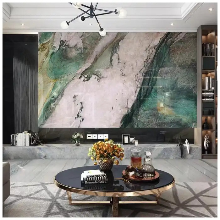
The purpose is not to calculate universal transmission from a phone photograph. It is to compare zones within the current slab and identify where a full-size mock-up must go deeper.
Record light-off and light-on states
A successful feature wall must remain coherent when lighting is off. Photograph the front face under intended ambient light, then the transmitted-light condition. Some slabs become dramatic only when illuminated and dull when not. Others hold enough mineral depth in both states.
The existing Exotic Quartzite Slab Selection guide helps choose full faces before this technical map begins. Translucency is one property inside a larger material decision, not the only reason to select a slab.
Mark repairs and fissures separately
A resin-filled fissure may transmit light differently from surrounding quartz. A reinforced area may cast a line. Some changes are acceptable and even visually interesting; others land in the middle of a focal panel and remain distracting. The map should disclose them before cut approval.
The Light Box Is Part of the Stone Composition
The active parent, Exotic Quartzite Slabs: Mineral Depth, Full-Face Selection, Finishes, Light, and Fabrication, keeps the stone decision tied to finish, repairs, cutting, and support. A backlit wall adds another assembly behind that slab. Light source, cavity depth, diffuser, ventilation, drivers, access, frame, and panel fixing all affect what the room sees.
Cavity depth affects uniformity
A shallow cavity can reveal individual light points or linear bands. More distance and suitable diffusion may help light blend, but available depth, efficiency, heat, support, and access place limits on the system. There is no honest universal LED spacing for every stone and wall.
The lighting mock-up turns quartzite translucency mapping into an assembly decision. I include the proposed diffuser, frame color, joint material, cavity lining, and dimming range. A white test box and a dark finished frame can produce very different brightness around the same slab edge.
Color temperature changes mineral color
Warm light can pull amber, cream, and iron-toned areas forward. Cooler light can make pale quartz feel icy and sharpen dark structures. Dimming may change perceived contrast. I test more than one setting when the design expects both evening atmosphere and daytime clarity.
A Champagne quartzite slab may respond beautifully to warm transmitted light, yet the same setting can flatten subtle grey structure. The mock-up decides. A material name does not.
Supports can cast their own drawing
Frames, rails, clips, pads, and adhesive zones may become visible through the stone. Their locations belong on the light map. The structural design and fixing method must follow the responsible engineer, fabricator, system provider, and applicable project requirements.
I prefer supports that respect natural opaque areas where possible, but visual preference cannot override engineering. The solution may require a different panel division, a different support concept, or acceptance of a visible shadow line.
Overlay the Cuts before the Best Light Disappears
Place focal panels first
Assign the most important viewing areas before secondary returns and concealed pieces. A strong translucent window belongs where the room can read it. It should not be consumed by a door opening, television recess, or service panel unless the design intentionally frames it.
When several slabs are available, quartzite translucency mapping helps allocate them by role rather than rank them from best to worst. One face may carry a bright central window for the focal panel. Another may offer quieter edge light for returns. The composition becomes richer when each slab is used where its response makes sense.
Check every joint in both light states
A joint may be quiet under front light and dark under transmission because sealant, backing, or frame blocks light. Mitred corners can brighten or shadow unexpectedly. Include joint materials and widths in the mock-up rather than displaying two loose slab pieces with no real connection.
Preserve access
Drivers and lighting components need a maintenance route that does not require breaking the stone. Removable panels, accessible ceiling zones, side access, or another engineered method should be coordinated before the wall closes. True luxury includes the ability to service what makes the stone glow.
The Hard-Won Lesson: A beautiful bright zone can hide the service opening
The strongest translucent area sits exactly where the lighting drawing places a removable access panel. Moving the access after fabrication would cut through the frame and change the support path. Keeping it would divide the brightest mineral window with a permanent shadow line. Both drawings were individually complete, but nobody overlaid them before cutting.
The Lesson: Combine the translucency map, panel cut map, support frame, and maintenance access in one release drawing.
A Good Backlit Wall Still Looks Like Stone
Do not chase uniform brightness
Opaque branches, pale windows, quiet clouds, and changing crystal depth are the reason to use real quartzite. Forcing every zone toward one brightness can erase the composition or produce obvious hotspots. The light should reveal geology, not compete with it.
A completed quartzite translucency mapping record also protects the light-off state. I compare the selected panels under ambient light before final release. If the brightest transmitted zone belongs to a face that looks weak or heavily repaired without illumination, the project must decide which condition matters more during normal use.
Compare natural depth with manufactured repetition honestly
The permanent comparison, Natural Quartzite or Marble-Look Sintered Stone for Premium Interiors, separates authentic mineral depth from controlled manufactured pattern. A project may value consistency or natural variation differently. Backlighting makes that distinction especially clear.
Escalate before changing stone or light on site
If an installed panel shows hotspots, dark grids, or an unexpected repair, photograph the full wall with light off and on. Record dimming level, color setting, panel ID, and affected coordinate. Do not grind the back, replace drivers, or alter supports while the cause is unclear. Compare site conditions with the original map and mock-up.
Any approved correction should update quartzite translucency mapping. A changed driver, diffuser, panel thickness, support rail, or replacement slab can alter the transmitted pattern. The revised record gives maintenance a new baseline instead of leaving future teams to compare the wall with photographs from a different system condition.
I retain light-off, full-output, and normal-dim photographs after commissioning. Those three states describe the wall more honestly than one dramatic night image and give maintenance a practical reference when output changes over time.
I keep my approved map with the slab record, and our fabricator receives the same revision. We update it after any accepted system change.
Quick-Reference Checklist for Translucent Quartzite
- Photograph the complete front and back of every candidate slab.
- Apply a coordinate grid that follows the physical slab orientation.
- Test transmitted light under recorded and repeatable conditions.
- Mark bright, moderate, opaque, repaired, and reinforced zones.
- Overlay panels, openings, joints, frames, supports, and access.
- Build a representative full-size lighting and joint mock-up.
- Approve the composition with lights both off and on.
Frequently Asked Questions
1. Are all quartzite slabs translucent?
No. Translucency varies by mineral composition, crystal structure, thickness, fissures, repairs, reinforcement, and the test light. Even one slab can contain bright windows and opaque structures. Test the current full face rather than relying on the material name.
2. Does thinner quartzite always look better when backlit?
Thinner areas may transmit more light, but thickness also affects fabrication, handling, flatness, support, and structural behavior. Do not reduce thickness solely for brightness. Use material-specific testing and the responsible fabricator and engineer’s requirements.
3. Can mesh or resin be seen through backlit stone?
Yes, some mesh, resin, fiberglass, repairs, adhesives, and markings can create shadows or color changes. Inspect the back and test the proposed assembly. Disclosure and careful panel allocation are more reliable than assuming the reinforcement will disappear.
4. What should quartzite translucency mapping include?
Include slab ID and orientation, front-light image, transmitted-light zones, back condition, thickness, repairs, reinforcement, panel boundaries, openings, joints, supports, light-box components, access, and the approved mock-up settings. Keep the coordinate system consistent through fabrication.
5. What is the first step when a backlit wall shows dark bands?
Photograph the full wall with lighting off and on, then record panel IDs, dimming level, color setting, and band coordinates. Stop unapproved changes. Compare the pattern with support drawings, LED layout, diffuser, joints, repairs, and the original slab map before assigning a cause.
Final Conclusion
Kuarzit translucency mapping turns a vague promise of glow into a visible record of mineral response, back condition, cuts, joints, supports, and light-box constraints. Test the whole slab, preserve its coordinates, and approve a real assembly with lights off and on. This stone has been waiting for millions of years; MQ STONE would rather let its bright and dark passages speak honestly than force every part of it to glow the same way.
References
- Dimension Stone Design Manual, Natural Stone Institute.
- ASTM C616 Standard Specification for Quartz-Based Dimension Stone, ASTM International.
- ASTM C97 Standard Test Methods for Absorption and Bulk Specific Gravity of Dimension Stone, ASTM International.
- ASTM C880 Standard Test Method for Flexural Strength of Dimension Stone, ASTM International.
- IES Lighting Handbook, Illuminating Engineering Society.
- Lighting for Interior Architecture, Chartered Institution of Building Services Engineers.
- Architectural Stone Fabrication and Installation Guidance, Natural Stone Institute.